|
Solid Angle Calculator V-2014091607 Microsc. Microanal. 20, 1318 - 1326, 2014 doi:10.1017/S1431927614000956 |
|
|
|
Solid Angle Calculator V-2014091607 Microsc. Microanal. 20, 1318 - 1326, 2014 doi:10.1017/S1431927614000956 |
|
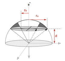
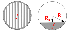
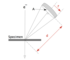 Radial Detector, Tilt Angle (θ) = 0 |
|
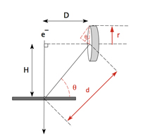 Non-Radial Detector, Tilt Angle (θ) > 0 |
||||||||||||||||||||||||||||||||||||||
 Radial Detector, Tilt Angle (θ) = 0 |
|
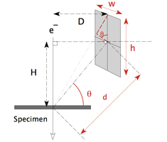 Non-Radial Detector, Tilt Angle (θ) > 0 |
||||||||||||||||||||||||||||||||||||||
|
|
|||||||||||||||||||||||||||||||||||||||
 |
|
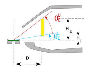 HL which is negative ( i.e. below the specimen plane) |
||||||||||||||||||||||||||||||||||||||
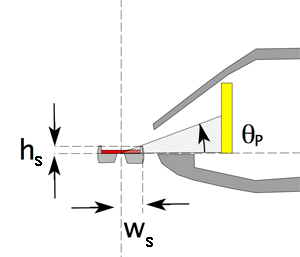
 Moxtek Grid Holder Penumbra Moxtek/Holder/Collimator Penumbra Notes:
|
|
|||||||||||||||||||||||||||||||||||||||